|
|
Post by Oldtimer on Dec 3, 2020 9:13:08 GMT -8
|
|
|
|
Post by Oldtimer on Dec 7, 2020 14:40:14 GMT -8
The subtleties will kill you on a build like this. Both the chassis donor and the body donor are, more or less, Plymouth B-bodies, and both are Ertl. So, what could go wrong? When I initially bolted the GTX body onto the Roadrunner chassis, there was an interference that did not allow the hood to close. As a matter of fact, it stuck up at about a 30 degree angle. WTF, Over? (I worked with a bunch of ex-Air Force guys for a while). If you are familiar with this era of diecast, hoods, doors, and trunks (when they open) all have dogleg hinges. One would think that if you've seen one hood dogleg, you've seen them all, especially if the models appear to be identical. In my case, the doglegs of the GTX body donor were thicker than the doglegs for the Roadrunner, and would not clear the Nascar chassis cowl air induction. So, I swapped hoods between the two models, and, Eureka! A few progress shots follow.     One thing I am going to half to solve is whether to simply drill two holes and allow the roll cage to tie into the package tray, or carve out slots in the package tray to allow the roll cage bars to attach back to the donor interior.  |
|
|
|
Post by Oldtimer on Dec 21, 2020 12:13:37 GMT -8
So, I took a step back from this one, and pondered my options. Here is the set of models that I have access to for this project. 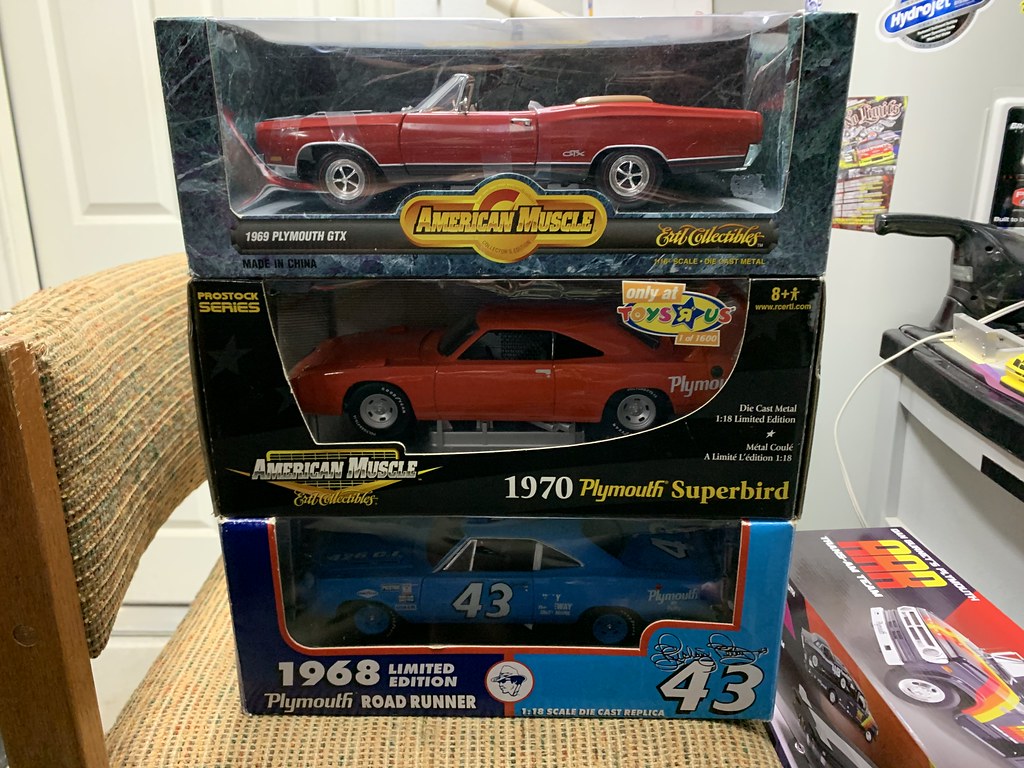 The top one, of course, is the body donor, the next two are a Toys R Us exclusive Nascar Superbird and the initial potential donor, a Petty Roadrunner.    Well, just the other day, I was able to score another TRU Superbird, and upon delivery, I got this.  So, in a lemon/lemonade funk, I decided to take it apart and see what it looked like as the chassis donor. One thing about the Ertl Superbird mold is that you have to remove the rear wheels in order to access a screw in that wheel well. I was able to acquire a tool that helps in removing those wheels, and with little bit of effort, was successful. The issue is that the rear axle has a mushroom head with a slot, and you have to compress that slot to get the wheel to pop off. Looks good from the top. I particularly like the black interior against the red exterior. If I am lucky, no painting on this one, only decals.  Before I put the wheels back on, I made a test fit. Looks good from the side, as well. Getting excited about this build.  So popped the rears back on to get an idea about stance and rake.  
Now that I have a clearer definition of the body/chassis donor relationship, the build can continue. Stay Tuned! |
|
|
|
Post by Oldtimer on Dec 23, 2020 9:41:57 GMT -8
Made some progress, at least in the disassembly stage. On the Superbird, there's an extension of the under tray to support the nose.  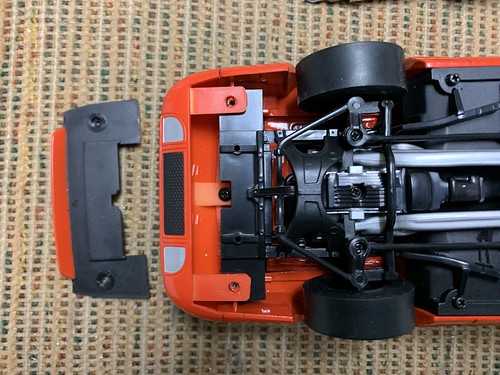 I had to remove this much of it to get the original test donor body to fit.  Here's our new body donor, straight out of the box.  Chassis ready to be recycled.  Underside of the body.  Knew it wasn't going to fit, but just for frame of reference.  I know from playing around with the original body donor, that these tabs will interfere.  So, a little bit of Dremel later.  Test fit again, but still some interference that I was expecting.  I knew a couple of other things would have to be removed and/or eventually modified, such as the dashboard and the hood (due to the discrepancy in the dog leg hinges noted above.  With those two elements removed, we now can proceed to see what needs to be put back on, and to what extent it will need to be "adjusted". On of the thing I will do is see if the dashboard from the Superbird will help. Can't use the Superbird hood, though, as I am going for a no-repaint solution. 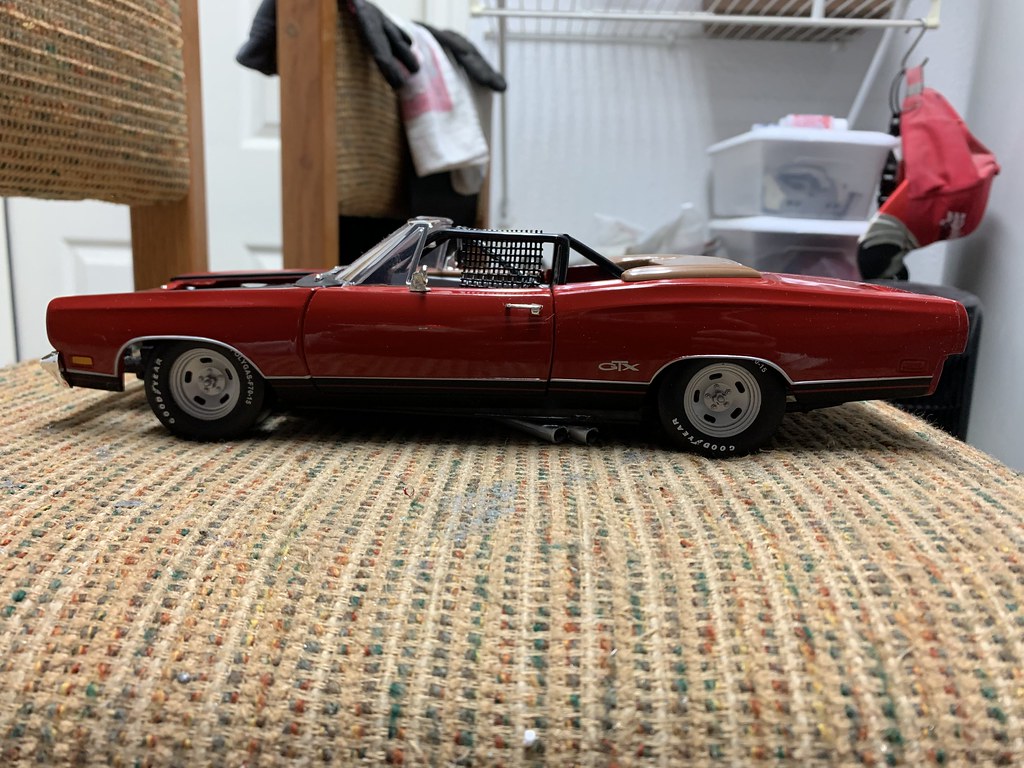
Stay Tuned! |
|
|
|
Post by Oldtimer on Jan 26, 2021 8:00:12 GMT -8
Been looking at this one on my bench for too long, so thought I would concentrate on it for a few days. One issue to deal with is that the body donor chassis has front inner fenders and the chassis donor chassis does not. When you set one upon the other, you see the gap. However, the donor Superbird chassis does have a front roll cage bar around the engine compartment.  However, it makes the body sit too high, as the only place it supports is in front of the radiator.  If you remove it, the body sits way too low, and we start getting into our clearance problems with the hood.  My solution was to remove the front hoop, and make it adjustable. I added aluminum extensions to the hoop supports, and placed pins in the chassis locations.   This way I can adjust the height and get the body rake correct. For ease of construction, I have used a similar pin and hole attachment for the firewall. Previously it was glued in, now it is removable. I will permanently install it at the final.    Next I will take up creating a tonneau cover for the rear of the cockpit.  |
|
|
|
Post by Oldtimer on Jan 27, 2021 8:39:53 GMT -8
Rough first pass - tonneau cover 

|
|
|
|
Post by Oldtimer on Feb 25, 2021 13:16:52 GMT -8
So I am back on this one, as the Camaro project rests in pieces. I have been working on getting the front roll cage hoop modified to allow the body to sit correctly on the chassis. I added an extension to the nose of the chassis, made out of a piece of styrene angle.   Then I fabricated some connectors out of aluminum tubing to stabilize the mounting points.  Here's the hoop mounted to the chassis (temporarily). Once we go final, all the aluminum will be gloss black to match the chassis. 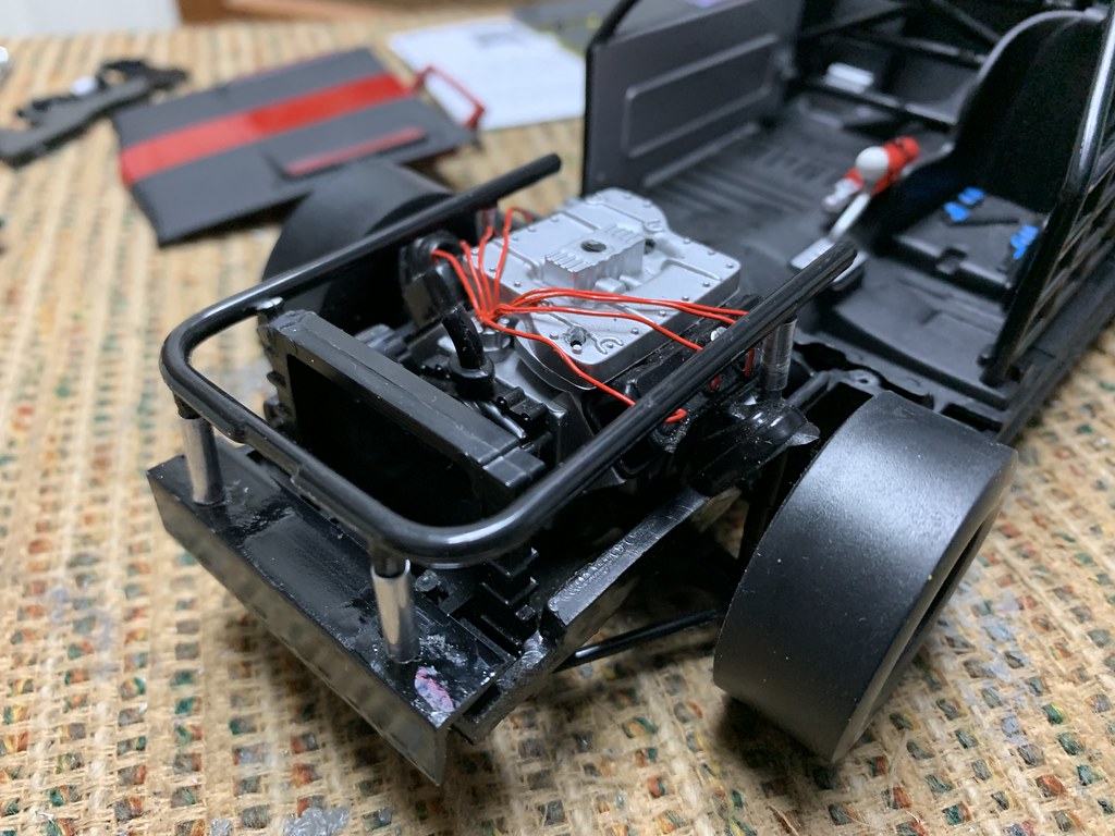  Had to relocate the radiator filler neck. Here's how it looked before, and after.   So I thought I was in pretty good shape, until I sat the body back down on the chassis. With the front hoop installed, it just doesn't want to fit right. There is interference between the hoop and the diecast radiator bulkhead. As you can see from this set of pictures, it was like the Tall Man from Cornwall.    So the bulkhead had to go!   
And now, without it, the body sits way too low.  So I fabricated a hanger out of brass angle.   And thar she sits!    
Decals shipped today, so going to wait on anything else until they get here. |
|
|
|
Post by Oldtimer on Mar 1, 2021 10:53:33 GMT -8
So, one step forward and two steps back!  Well, my piece of brass angle just didn't want to stay in place, so I drilled a couple of 3/32" holes and pinned it in place with a couple of #00-90 brass machine screws.   Plus, as you can also see in these pictures, the plastic angle holding the front of the engine hoop interfered with the bumper, so I had to cut it back quite a bit. However, now the bumper fits.  But the hood doesn't, as the heads of the screws hold it up too high.  So, me and Dr. Dremel went to work. First, I tried to relieve the area right above the screw heads with an 1/8" drill bit, but that didn't work, so got out a cutting wheel and went to work.  That's got me close, but still a little bit more needs to be shaved off. 
Stay Tuned! |
|
|
|
Post by pnance26 on Mar 22, 2021 12:51:59 GMT -8
Great work at finding solutions to problems.
I always thought this was one division that NASCAR should have brought back at the 50 th anniversary.
|
|
|
|
Post by tatocorvette on Mar 22, 2021 20:24:51 GMT -8
Just a crazy idea, but can you put the screws from the bottom up and shave the excess on top flush with the bar?
Thanks,
Ismael
|
|
|
|
Post by Oldtimer on Mar 23, 2021 8:08:49 GMT -8
Just a crazy idea, but can you put the screws from the bottom up and shave the excess on top flush with the bar? Thanks, Ismael That's a good idea, however access from below is limited. What I have done so far is to source some countersunk head flat top screws, and working to see if I can get that to work. Thanks, and Stay Tuned. This one might be getting close. |
|
|
|
Post by garydavis on Apr 4, 2021 11:39:57 GMT -8
This is sure looking good O.T. It's cool watching you work with the 18th metal. Looking forward to your next installment for sure.
|
|
|
|
Post by Joel_W on Apr 5, 2021 10:55:01 GMT -8
Jim,
One problem solved and or heading in the right direction, then another one pops up it's ugly head. So far you're winning the battle for sure. Can't wait to see how the engine compartment and roll cage all come together.
joel
|
|
|
|
Post by Oldtimer on Apr 19, 2021 14:17:56 GMT -8
Getting back on this one after a hiatus of sorts. After I mocked up the tonneau cover, I had to figure out both a way to install it, and how to replicate how they were installed on the real racers. You can see from these pictures (of which there are few in sufficient detail), it looks like they may have attached them with snap-type fasteners.   I searched all over for something I could use. I thought about photoetch, but couldn't find anything in 1/18 scale, plus attaching them was going to be a PITA. Then, one night, it hit me! Sewing pins! So, I drilled a pattern of holes in a final cover, and since my workbench also doubles as a bar stool, I proceeded to use it as a pin cushion.  The question then becomes how to install the cover onto the car. The convertible top is attached to the model with two screws.  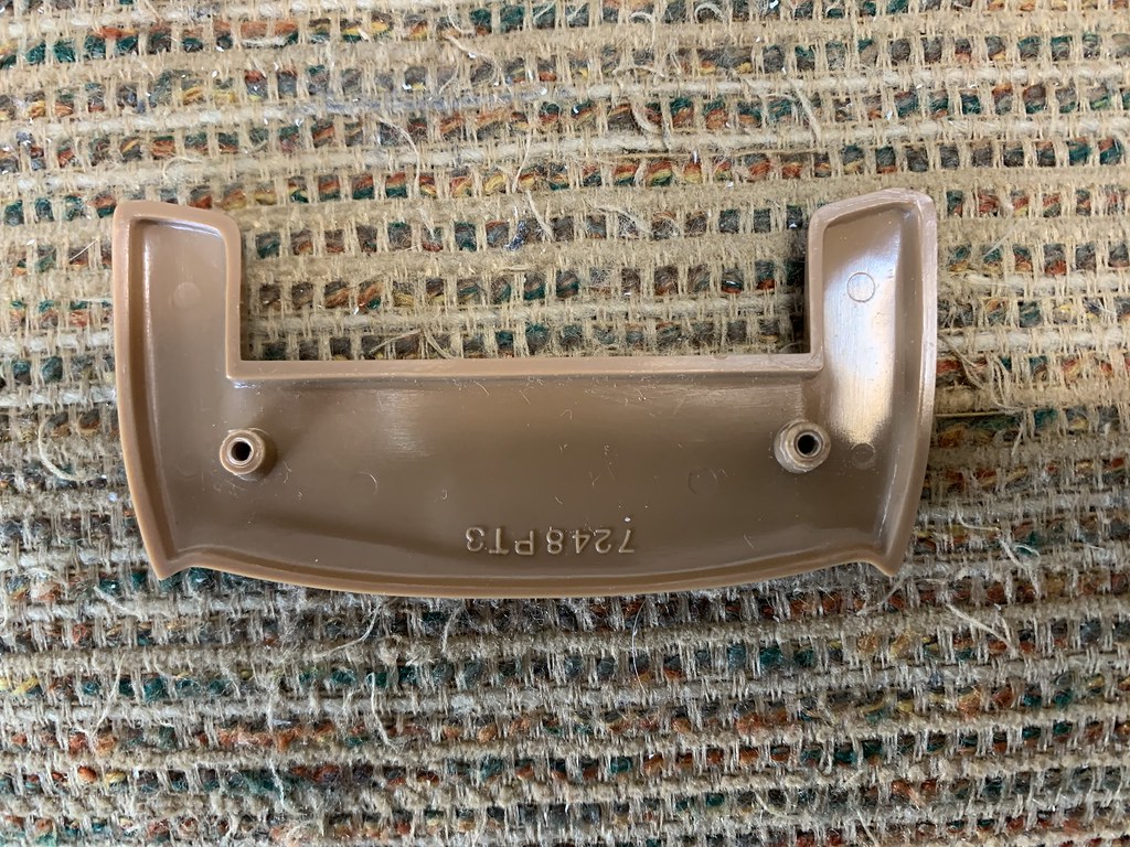  So, in lieu of drilling a couple dozen little bitty holes for the pins, I'm fabricating a mounting plate that I will glue to the tonneau cover, and use shortened screws to attach. 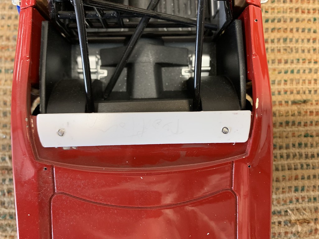 My plan is to then paint it Gloss Black and stick the pins through, hoping they will be captured by the paint. Then turn it over and trim the ends of the pins flush.  
Then I can get back to the body/chassis mounting. |
|
|
|
Post by Joel_W on Apr 20, 2021 6:28:41 GMT -8
I'd say that you've come up with an effective method to both fabricate and install the tonneau cover. Had one on my MGB and that's exactly how they were installed. Eventually from use it was common for a clip to rip as the fit was pretty tight coupled with the generated wind when driving at a shall we say a decent speed. My only question looking at the side profile is how are you going to get the cover to lay down over the surface of the car?
joel
|
|


