Revell 1/25 scale Roush SCCA Trans AM JPS Mustang
Dec 8, 2019 10:38:28 GMT -8
Chris K. Hale, Ben_B, and 1 more like this
Post by Joel_W on Dec 8, 2019 10:38:28 GMT -8
Finally, after two weeks without an update, I've got enough accomplished during this Holiday season to post another update. As I said in my last update, that polishing out the body shells was number 1 on my hit list, well, it just never happened. Just spent more time working on finishing up the engine compartment.
1st order of business was to glue the glass bukhead window in place, but 1st I had to paint the rubber glasket, which I did by hand painting Tamiya XF-69 Nato Black, then gluing it in place with Tamiya Extra Thin. Then glue the driver's compartment rear bulkhead to the chassis tubing. Turned out to be another gluing adventure. Only this time it was all my fault. The tubing is super glossy, and not even Tamiya Extra Thin would eat through all the layers of Tamiya X-1 Gloss Black. Then I tried CA glue, and it was basically another failure as it held, but would snap right off while working on the interior. So out came the 5 min Epoxy, a little scraping of the tubing, and the job was done.
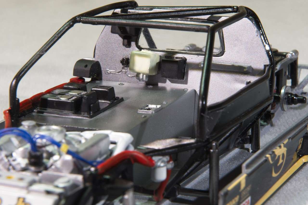
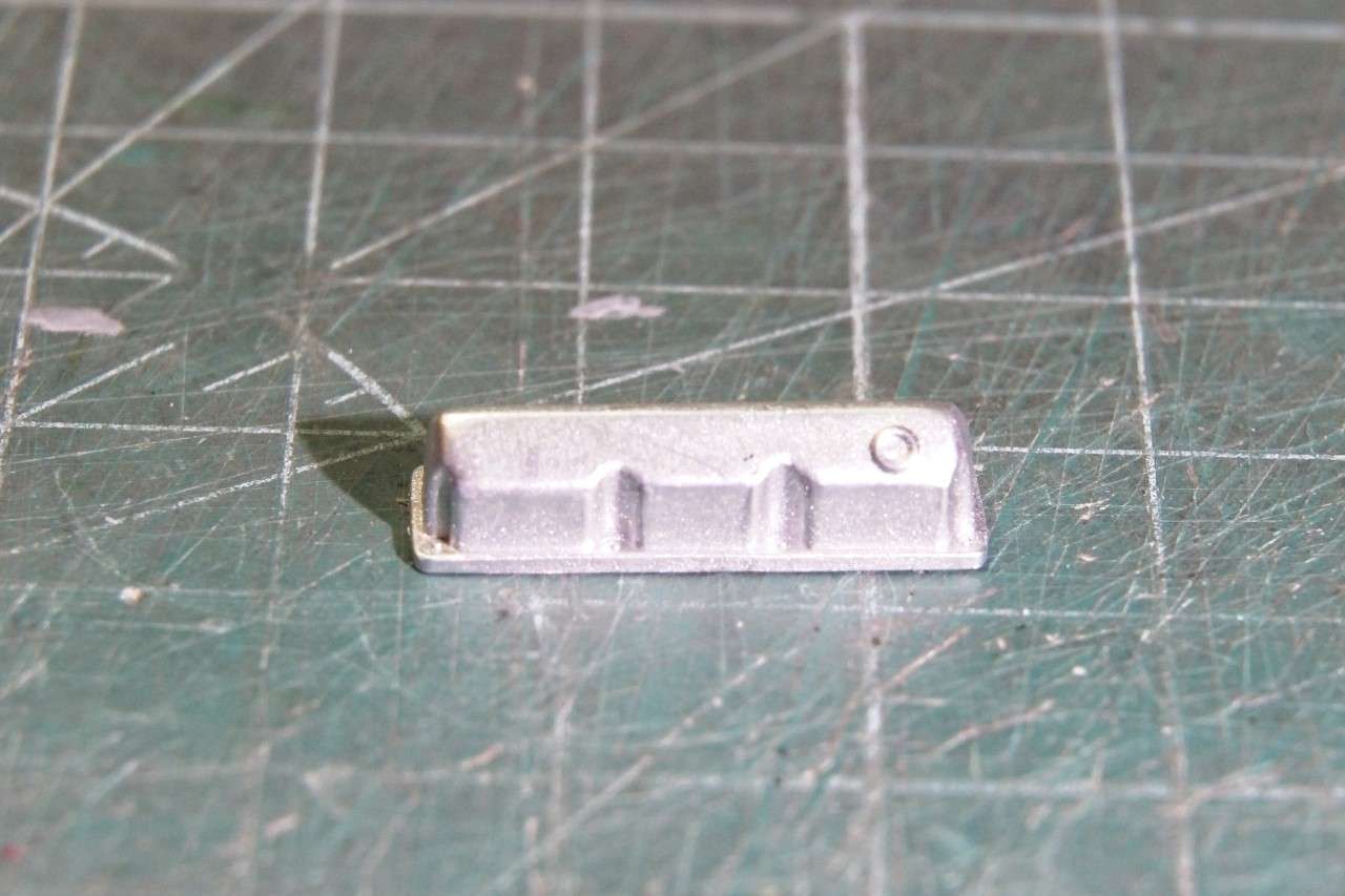
Now my undivided attention was focused on the engine/transmission sub assembly. The Roush Ford 358 ci V8 engine developed 650 hp running a single 4 barrel carb, and a Oil Dry Sump system. The kit parts fit basically well enough so that assembly was straight forward. However, the valve covers are the wrong ones, but I didn't have any spares so I used them with one modification. The breathers are just represented by a small raised circle?:
The Alloy Aluminum front plate was used as the main attachment points for the engine to the chassis, had some vaguely molded on parts that represented the ignigion coil and an over flow bottle. I just cut, filed, and sanded them off. I air brushed the plate Mr. Color Metalizer Steel, and then painted the water pump flat Aluminum. Unfortunately, I've never been able to really photograph the various shades of Aluminum Metalizer so that it looks like it does in person. This is the best I could do.

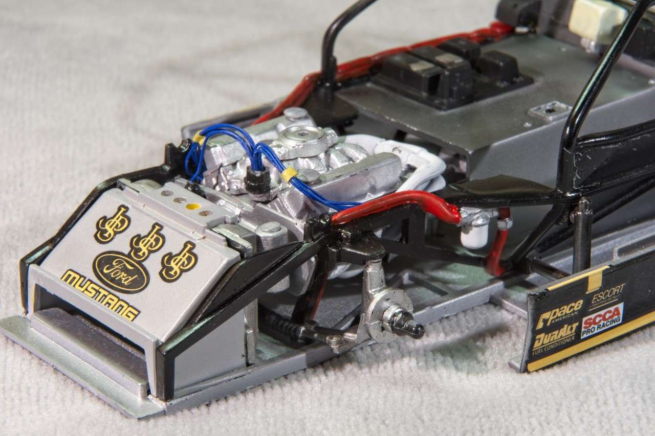
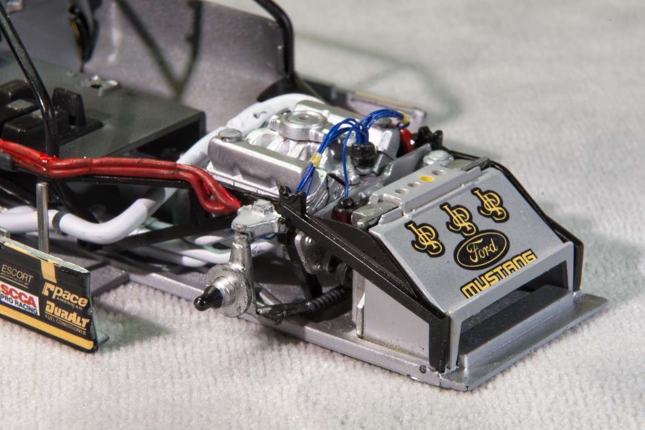
I made a ignition coil out of Evergreen tubing, and a little putty that was sanded to shape to represent the cone top. I used a generic bottle to represent the overflow bottle from my spares box. Unfortunately, I just forgot to photograph the assembly before installing the engine. I drilled out the distributor, and glued 9 Blue ignition wires for the plugs plus the one for the coil. Then glued the wires in place. The ignition wires are strapped and attached to the front of the valve covers on the real engine. I've wrapped them, but haven't as yet glued the wrap to the valve covers. I also used bits & pcs to make the breathers for the valve covers. If you look at the front of the engine, you can see the Aluminum mounting plate and on one side the over flow bottle, and on the other side the top of the coil with the ignition wire. You can also see that both Valve covers have a breathers made from more bits & pcs.
As for getting the engine/trans installed as it's a super tight fit was a major squeeze job, but ventually it does fit.
I didn't bother doing anthing with the carb other then gluing it on the top of the intake manifold as it will be completely covered by the air filter to be attached later. It's really more of a spacer then anything else.
As for the engine exhaust manifolds, they're each a 2 pc assembly that did require some putty and sanding. Then they were painted using the "Neat" method of no thinner so that it had a really rough texture to it. Installation was shall I say a little sloppy at best, but I did manage to get both installed and aligned, as well as the exhaust pipes which don't rearch the body panels. No big deal in my build as you can't see them once the main body is on. There is still a cross over pipe that I need to install to complete the engine exhaust system.
Originally I was going to add more lines to the engine compartment, but it's pretty tight with the engine installed, so this is going to be it unless I figure how to add a line here and there.
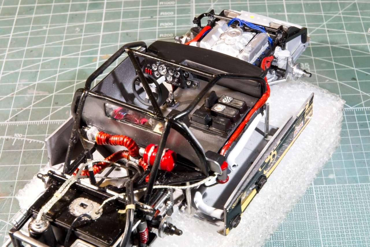
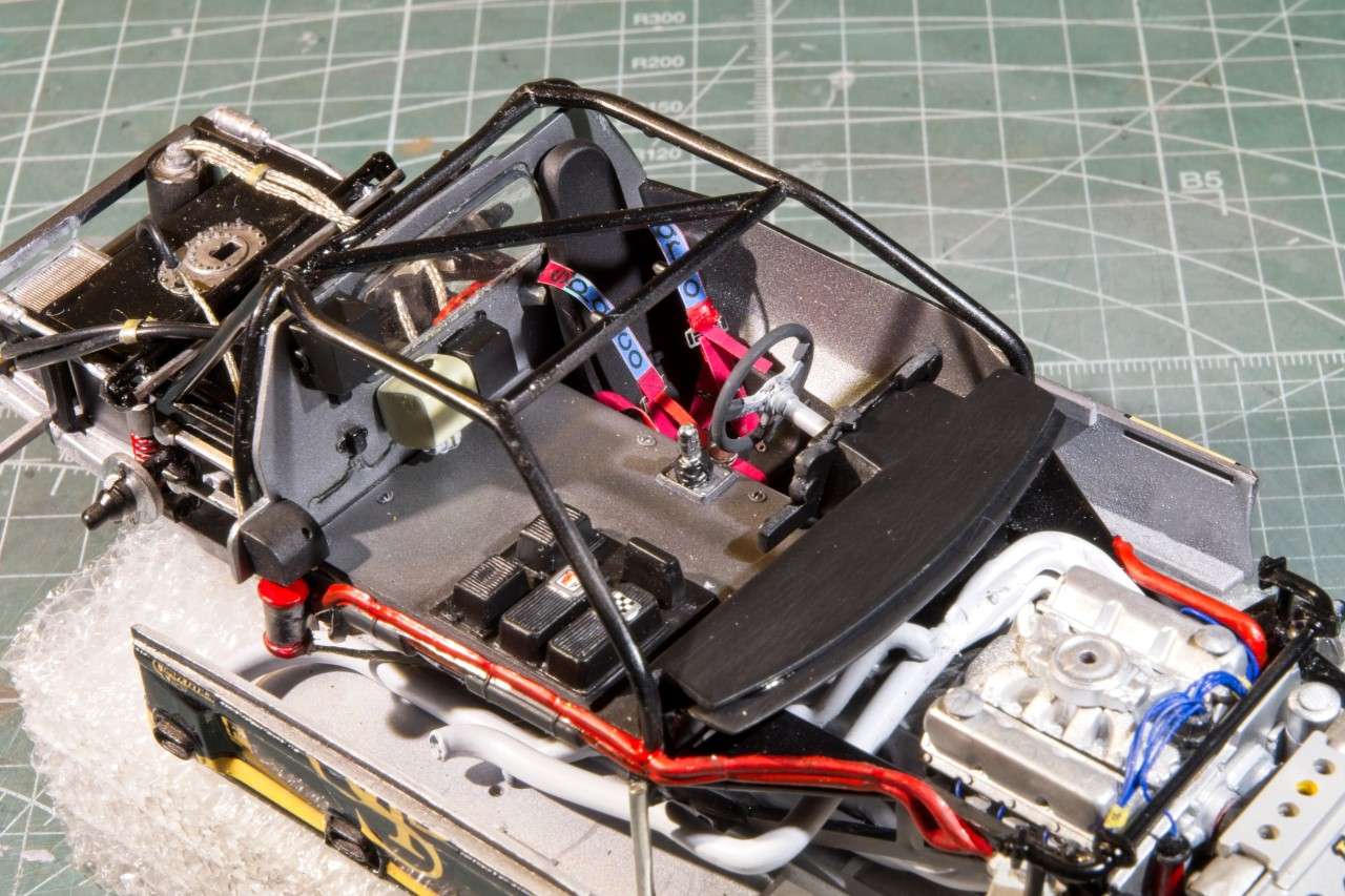
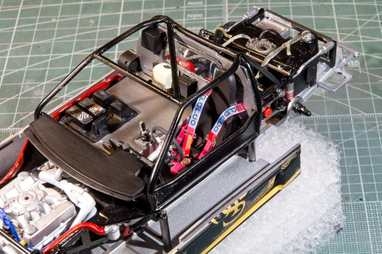
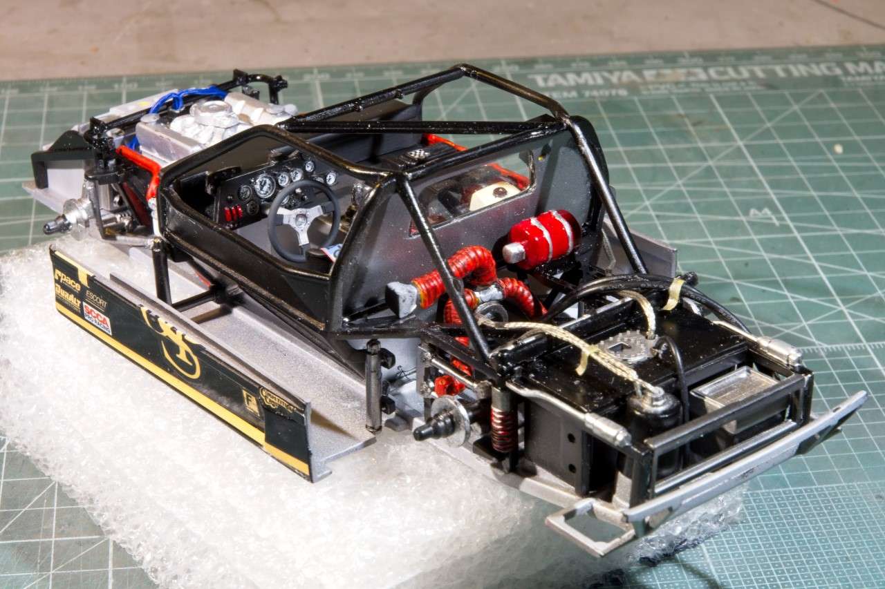
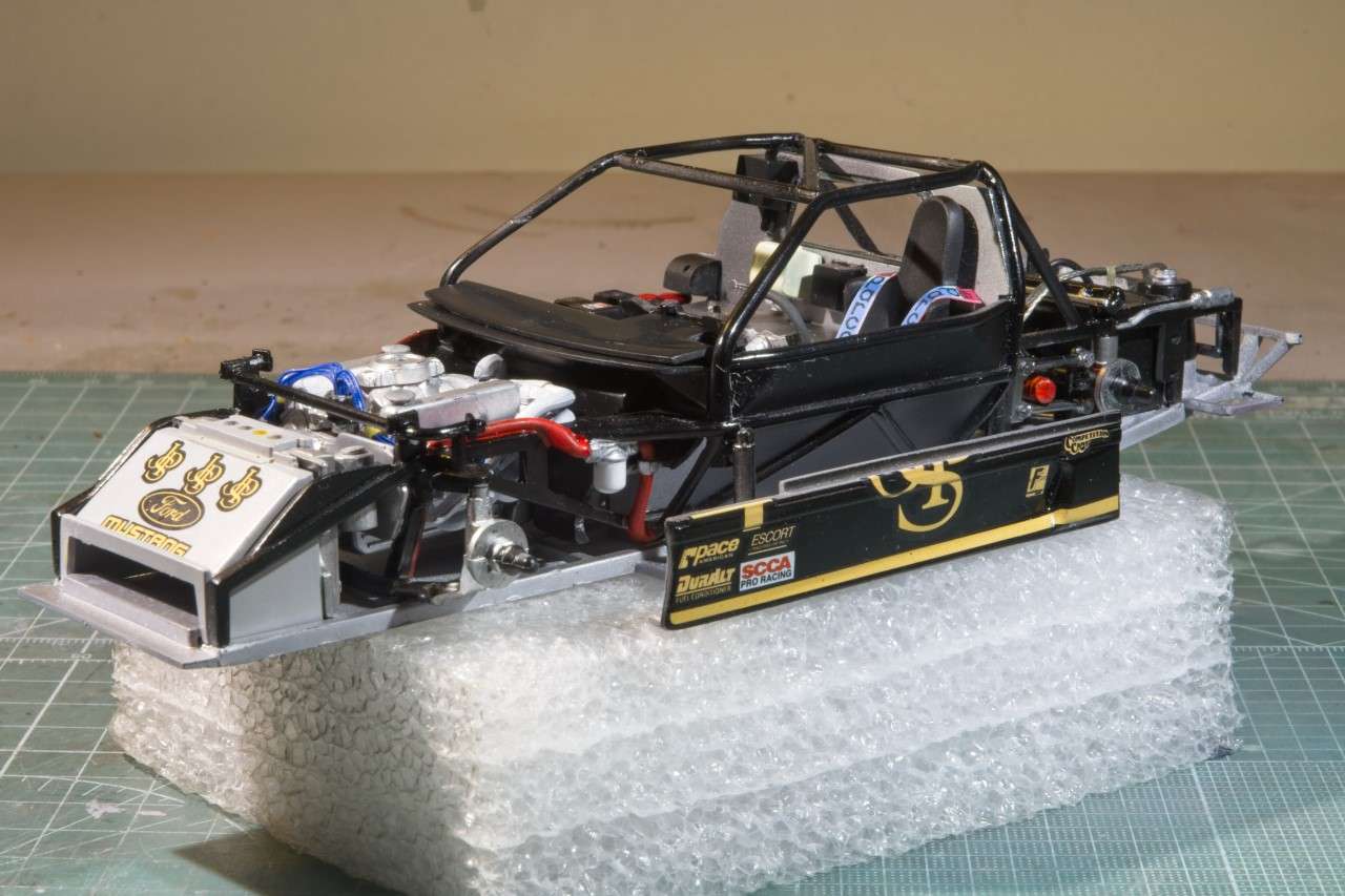
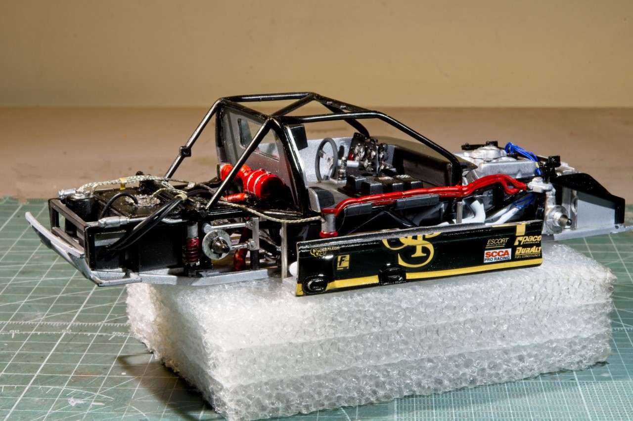
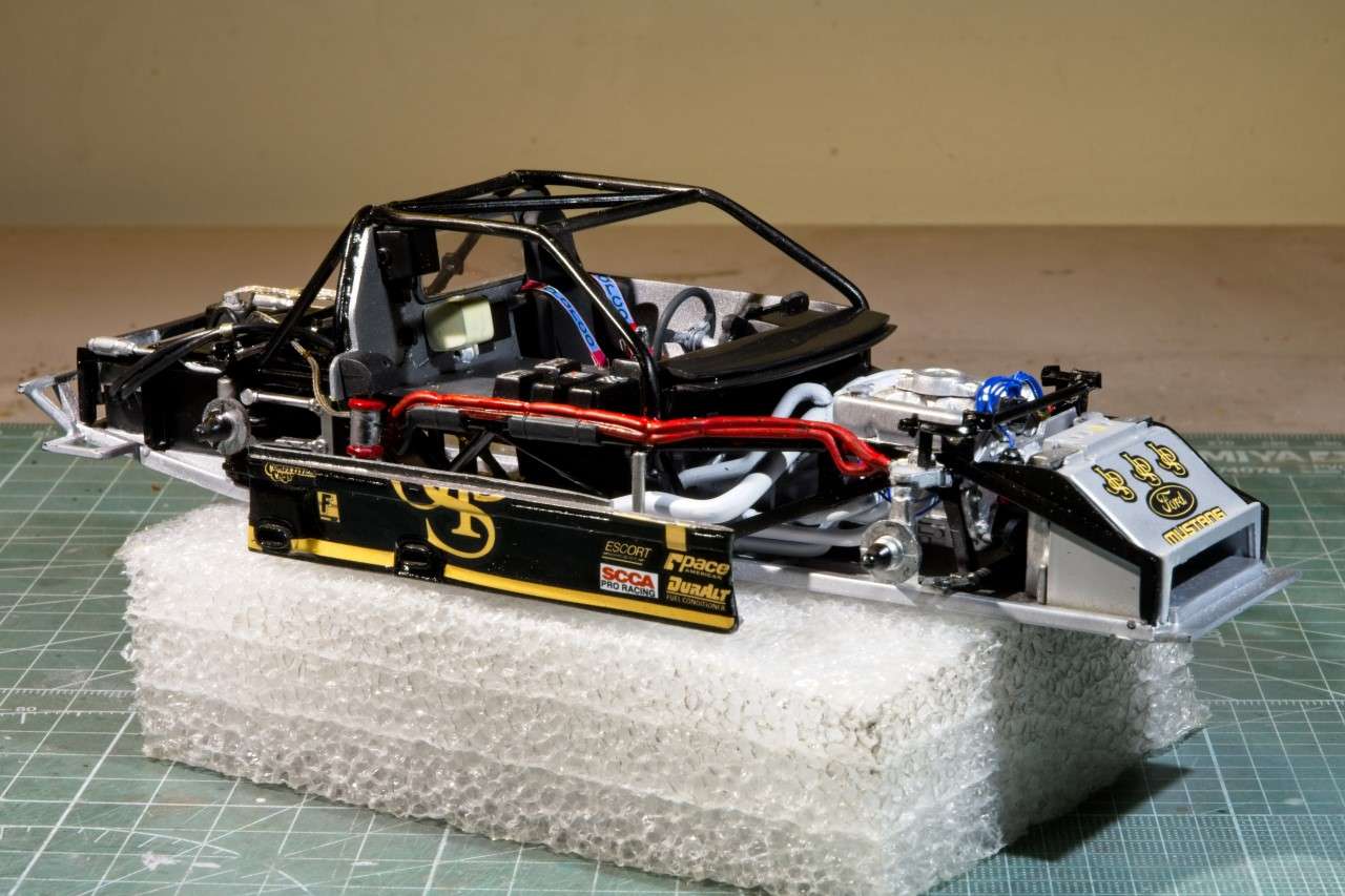
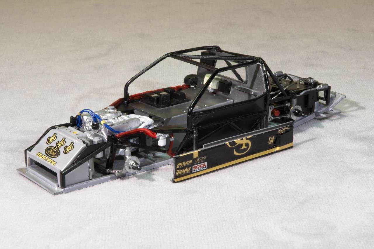
Here' a few pictures of the overall chassis assembly to date:
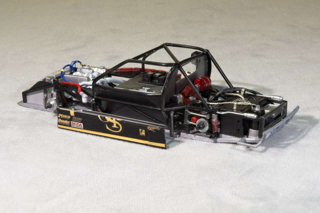
And 2 pics with the rear shell just dry fitted. Of course it's out of alignment as I must have done that while placing the chassis for pictures.
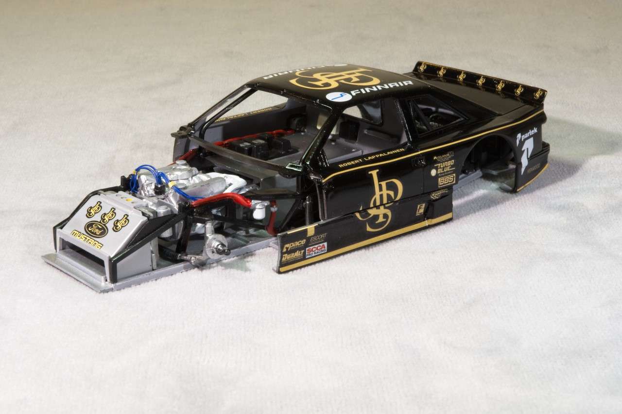

Thanks for taking the time to check out my build to date, it's always much appreciated.
Joel
1st order of business was to glue the glass bukhead window in place, but 1st I had to paint the rubber glasket, which I did by hand painting Tamiya XF-69 Nato Black, then gluing it in place with Tamiya Extra Thin. Then glue the driver's compartment rear bulkhead to the chassis tubing. Turned out to be another gluing adventure. Only this time it was all my fault. The tubing is super glossy, and not even Tamiya Extra Thin would eat through all the layers of Tamiya X-1 Gloss Black. Then I tried CA glue, and it was basically another failure as it held, but would snap right off while working on the interior. So out came the 5 min Epoxy, a little scraping of the tubing, and the job was done.

Now my undivided attention was focused on the engine/transmission sub assembly. The Roush Ford 358 ci V8 engine developed 650 hp running a single 4 barrel carb, and a Oil Dry Sump system. The kit parts fit basically well enough so that assembly was straight forward. However, the valve covers are the wrong ones, but I didn't have any spares so I used them with one modification. The breathers are just represented by a small raised circle?:

The Alloy Aluminum front plate was used as the main attachment points for the engine to the chassis, had some vaguely molded on parts that represented the ignigion coil and an over flow bottle. I just cut, filed, and sanded them off. I air brushed the plate Mr. Color Metalizer Steel, and then painted the water pump flat Aluminum. Unfortunately, I've never been able to really photograph the various shades of Aluminum Metalizer so that it looks like it does in person. This is the best I could do.

I made a ignition coil out of Evergreen tubing, and a little putty that was sanded to shape to represent the cone top. I used a generic bottle to represent the overflow bottle from my spares box. Unfortunately, I just forgot to photograph the assembly before installing the engine. I drilled out the distributor, and glued 9 Blue ignition wires for the plugs plus the one for the coil. Then glued the wires in place. The ignition wires are strapped and attached to the front of the valve covers on the real engine. I've wrapped them, but haven't as yet glued the wrap to the valve covers. I also used bits & pcs to make the breathers for the valve covers. If you look at the front of the engine, you can see the Aluminum mounting plate and on one side the over flow bottle, and on the other side the top of the coil with the ignition wire. You can also see that both Valve covers have a breathers made from more bits & pcs.
As for getting the engine/trans installed as it's a super tight fit was a major squeeze job, but ventually it does fit.


I didn't bother doing anthing with the carb other then gluing it on the top of the intake manifold as it will be completely covered by the air filter to be attached later. It's really more of a spacer then anything else.
As for the engine exhaust manifolds, they're each a 2 pc assembly that did require some putty and sanding. Then they were painted using the "Neat" method of no thinner so that it had a really rough texture to it. Installation was shall I say a little sloppy at best, but I did manage to get both installed and aligned, as well as the exhaust pipes which don't rearch the body panels. No big deal in my build as you can't see them once the main body is on. There is still a cross over pipe that I need to install to complete the engine exhaust system.
Originally I was going to add more lines to the engine compartment, but it's pretty tight with the engine installed, so this is going to be it unless I figure how to add a line here and there.
Here' a few pictures of the overall chassis assembly to date:


And 2 pics with the rear shell just dry fitted. Of course it's out of alignment as I must have done that while placing the chassis for pictures.


Thanks for taking the time to check out my build to date, it's always much appreciated.
Joel


